Deploying Fiber In The Home
February 29, 2024
Getting a fiber Internet connection to your home is a big deal! It’s probably the last physical connection you’ll ever need, due to the virtually unlimited bandwidth, stability, performance, and attainable speeds.
Having your ISP drop it off on the building entrance however is not enough. Wiring within a building is often needed, especially if you need to reach apartments, mechanical rooms, and all sorts of places where networking may be required.
In the spirit of DIY, as I’m the ISP, I decided to upgrade my existing wiring in my home and document the process here, for everyone to read, learn from, and enjoy. So to get started, let’s understand what we’re dealing with.
The building
The building I am installing fiber to has 4 floors, it has access to two streets, on opposite sides, and has three vertical paths that cut almost across its entire height. There are also two manholes, one on each street, where it’s possible to accept fiber optic cables from the outside world. Here’s a visual representation of that, using my advanced architectural design skills:
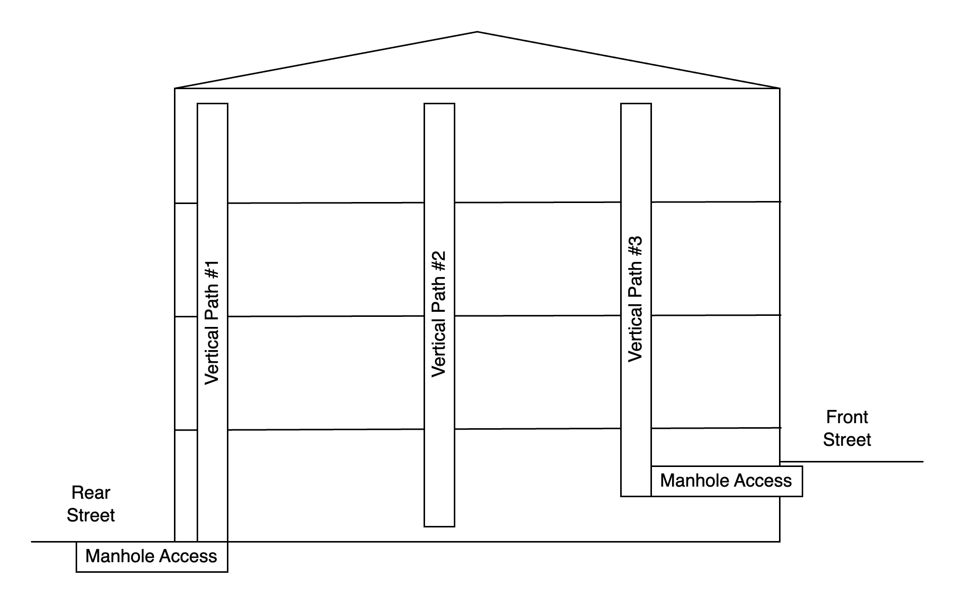
These vertical paths are either pre-existing, or they were created in previous work, and they allow for the easy traversal of cables within conduit across floors, following all building and safety codes. As buildings in Europe have concrete slabs and single or dual brick walls, insulation layers, pipes, cables, including within each floor, having these there helps immensly in implementation time, cost, and overall effort involved.
The design
Doing work on Layer 1 of the TCP/IP model is tedious and slow, requires extra materials that may not be in stock at home, and creates a mess. You’re drilling holes, have contractors over, and it’s also not really cheap.
For this reason, I wanted to use economies of scale, as well as a modular design. I decided to install something that’s beyond what I need today, but not by too much. I wanted to balance implementation time and cost with future expansion and usage.
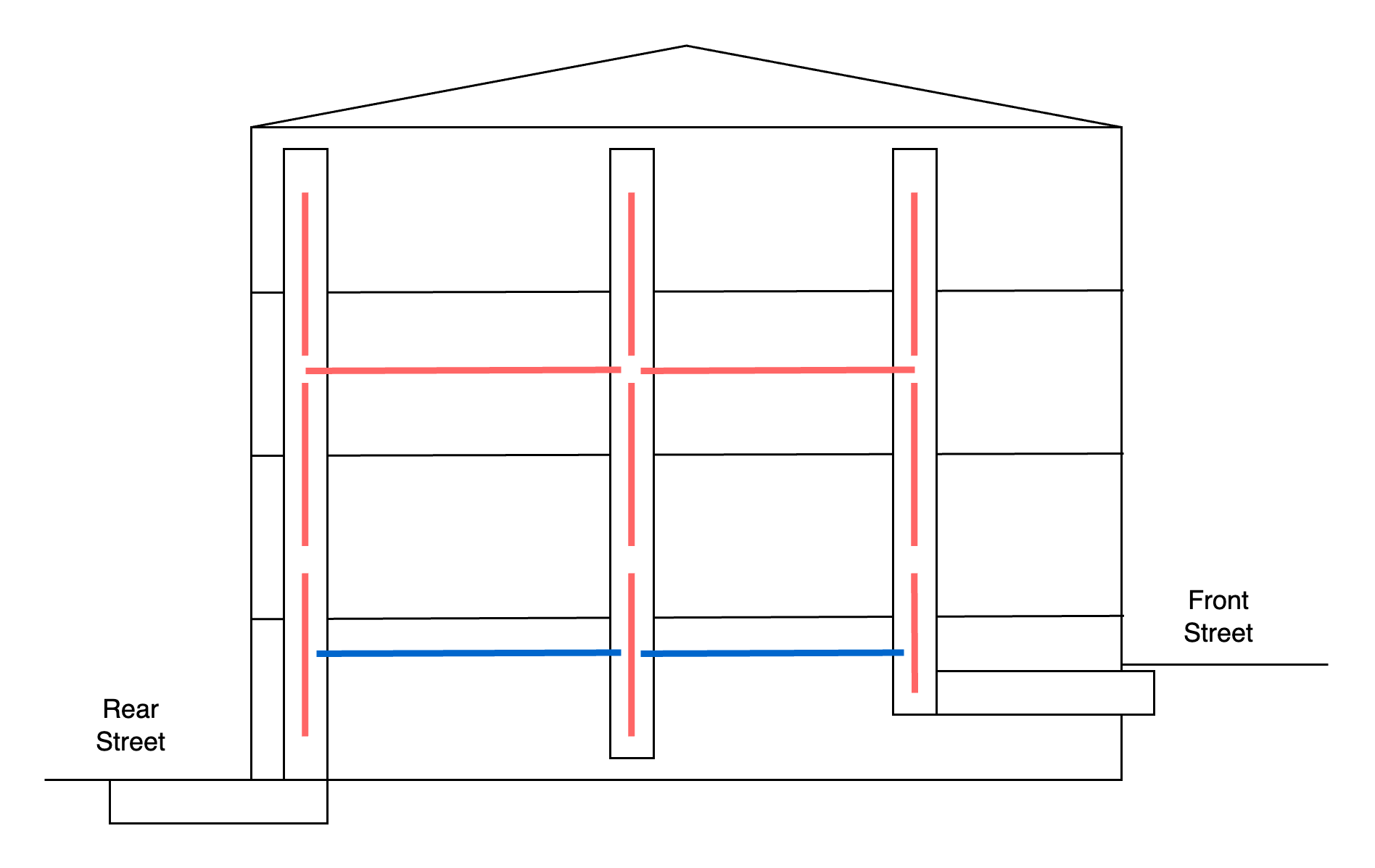
I therefore settled on the following cables:
Yes, I may have overdone it, but just by a little bit… :P
But what do these colors mean? Each red line is a cable that is installed. The two blue ones are spans of cable that couldn’t be installed, due to lack of time, and were left for a future date, if there is demand.
The two floors that have (planned) horizontal cabling were chosen due to their current use, as well as the ease of running cables across them without much too much disruption (visually, aesthetically, etc.).
The cable
It was time now to pick the cable to run across these conduits. Let’s go over all of its characteristics and explain how each choice was made.
Type of fiber
The main distinction is Single-mode fiber and Multi-mode fiber. The first one is cheaper on paper, it can work for tens or hundreds of kilometers, and it has practically unlimited bandwidth. It’s a single version, called OS2, and it’s the one that’s being used on almost every single outdoor application (between buildings, cities, countries, continents). The only advantage of the other option is in theory cheaper optics / lasers, but with the price of lower speed Ethernet (< 100 GbE) right now, it’s not really worth it. Multi-mode fiber comes as OM1, OM2, OM3, OM4, and OM5, and new standards are typically needed to support higher speeds.
For compatibility with other fiber installations, as well as all the pros and the lack of cons of single-mode, I decided to go with that.
Standard of fiber
Single-mode fiber traditionally had one category, G.652. This is split into G.652.A, G.652.B, G.652.C, and G.652.D. Each additional iteration increased the bar of manufacturing and certifying a cable and therefore led to better performance, longer distances, etc. FS.com has an article that describes the various specs of each version.
For any type of large terrestrial project, such as fiber cables installed on highways, train tracks, pipelines, and so on, G.652.D is preferred, and it’s also advertised as a competitive advantage over other networks in the area that lack the benefits that come with it.
One of the problems however of flexible glass that carries immense amounts of information using light is, naturally, bends. Light tends to travel in a straight line [Citation needed], and glass has to steer it around bends and curves by keeping it as close to the cable center as possible. If a turn is too tight, the light either can’t make it at all, or will do so at great signal loss. In a worst case scenario, the glass can also break, rendering this part of the cable unusable.
It is for this reason there’s another standard for single-mode fiber that’s called G.657. The two main versions of that is G.657.A1 and G.657.A2. The commercial name for that is bend-insensitive fiber. It’s practically fully compatible with G.652, so cables can be connected to each other, but it has lower losses when it’s turning around.
The term used is bend radius. Each cable comes with a number, in the millimeters, and it tells you what’s the tightest turn you can take and be within specifications. The FS.com article above links to an image that’s visualizing this, but since I cannot show it here, due to licensing restrictions, I’ll tell you about a tool I made and used for this project!
My friend Sandra in Zurich helped me by 3D printing the following designs I made:
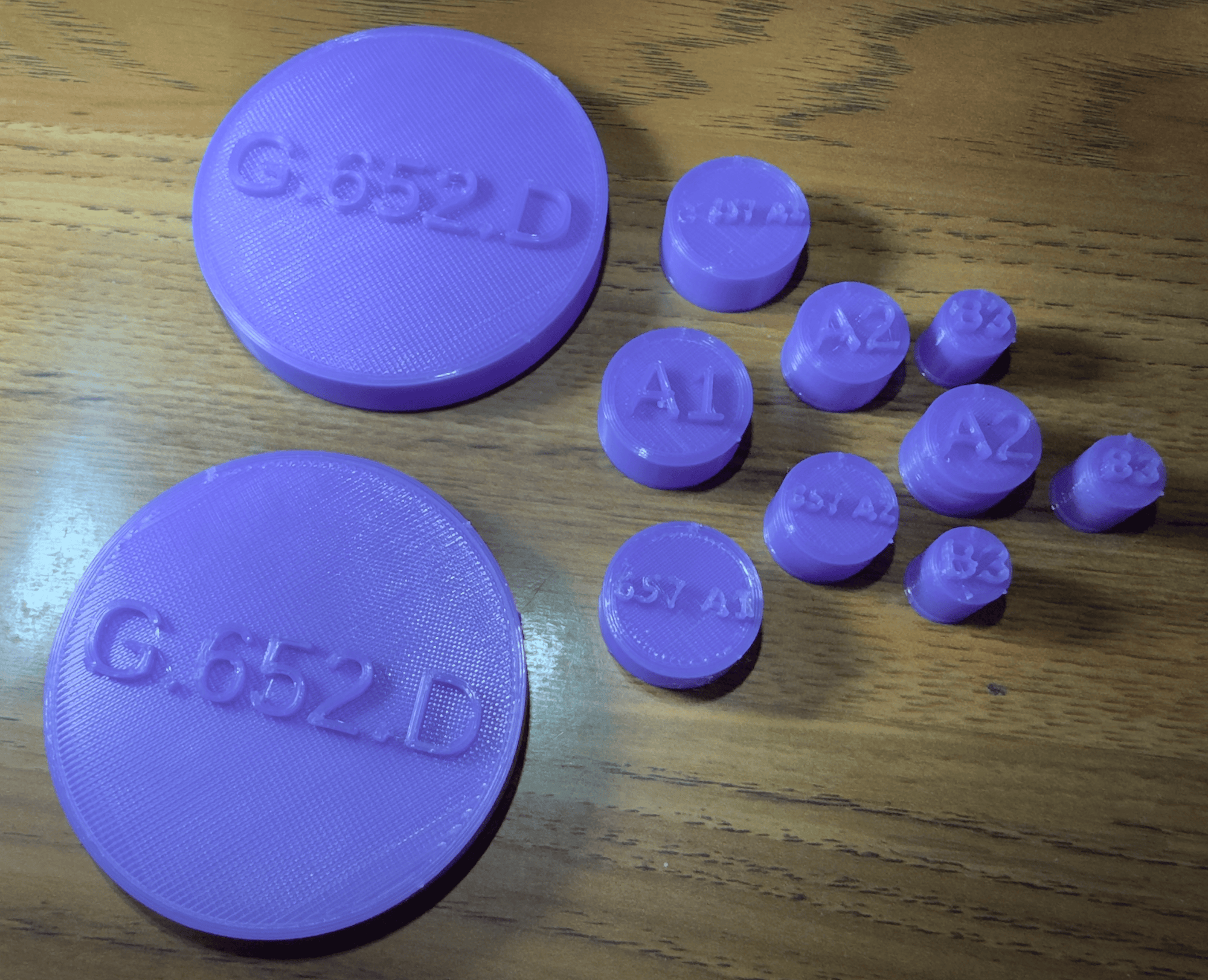
These are small plastic items, a few per standard, and every time you take a tight turn, you use these to check if it’s okay or not. Here’s an illustration:
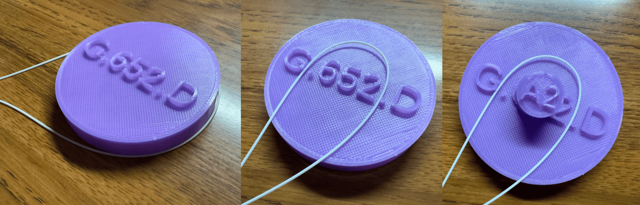
The first picture contains a proper G.652.D fiber bend, the second contains a too tight one, and in the final photo you can see the difference between normal and bend-insensitive fiber.
It’s commonplace in the region to install G.657.A1 within buildings, which is more expensive than G.652.D, but I went with G.657.A2. The cable has 7.5mm of bend radius, while the others would be 30mm and 10mm respectively. For what I’m doing, I can effectively have 90° turns without paying too much attention. If you’re already paying extra for A1, it’s not too much more expensive to get A2.
Fiber count
Unlike copper Ethernet cables, which are very bulky, warm up, are prone to interference and signal degradation, fiber optic cables are just tiny glass tubes. And since they’re very small, you can buy a single cable that has more than one of them inside. You then install the entire thing at once.
It’s common to find 1, 2, 4, 8, 12, 24, 48, 72, and 144 core cables. There are always other options too, but these are plenty for what I need anyways.
Since I am installing these across floors, and I want to provision additional resources, I picked the largest fiber count I could that wouldn’t increase the diameter of the cable. That number is 12, which will also come handy later down this project.
Cable protection
The individual fibers being installed are tiny. They are typically 0.9mm in diamater and that’s not the glass, over 90% of that is protection. Since they’re still fragile, they’re almost always being installed within another thicker protection layer. Copper cables for Ethernet have this too, as the 8 wires are then wrapped together to form one, but with fiber you don’t need 8 of them for a single connection, one is enough. They’re only bundled for scalability and reliability.
An important thing to follow here is safety and other types of rules. The material of the cable may have to adhere to certain regulations so your building can remain legal and maintain its insurance policy. This is primarily for fire safety where the cable must not produce toxic smoke when burned, be resistant to fire, and possibly also burn slowly. I am not going to advise you on that, look up the local rules, and follow them. They may differ on whether this cable is used for vertical or horizontal installation, whether it goes through (Layer 1) firewalls, etc. For my case, for simplicity, I went with a single type, that was good enough for all potential usecases.
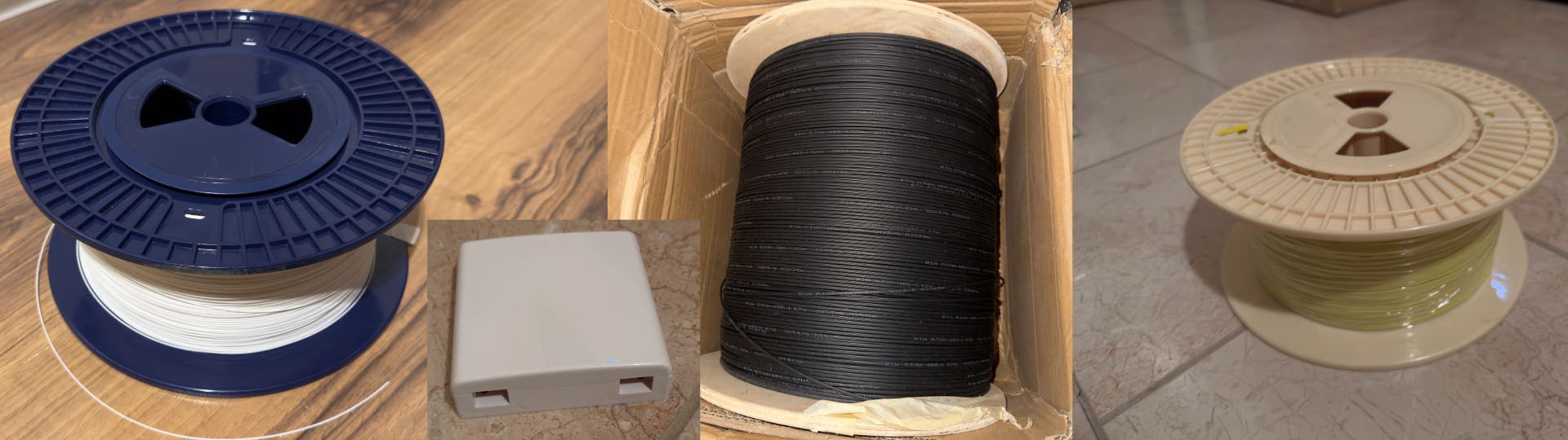
After stripping away the two tubes, and moving the kevlar to the side, here’s what I ended up with:
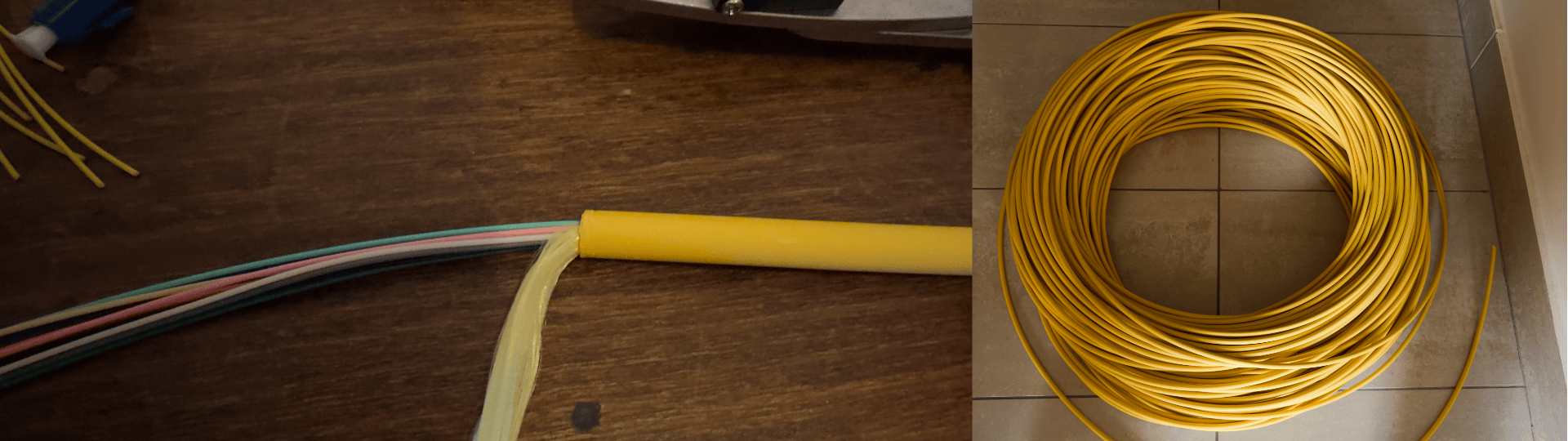
On the left you can see the 12 optical fibers within the yellow plastic, and on the right you can see the 300 meters I ordered for this project. Not all of that was used, but it’s good to have some extra for future work :)
As you can see, just like with copper, fibers are also colored, just differently.
Branching
The keen reader may have noticed that I am installing 11 cables on the property, and not one. Moreover, if I wanted an Internet connection on the top floor, there’s no direct path to the street manholes at the bottom to get there.
This was done on purpose, and the primary goal is modularity. There is cable between the top and bottom floors, it’s just in pieces. If you connect two or more of these 11 runs together, you can interconnect everything.
Let’s go over the physical installation to better understand how that works.
Termination Boxes
In each end of a cable there is a metal box, where the 12-core run enters. The
size of that depends on how many of them end up in the same location, but it’s
not too large and naturally blends in the environment it’s okay. It can be
mounted in a wall, hidden behind or inside furniture, or otherwise be
professionally installed. The ones I am using look something like this:
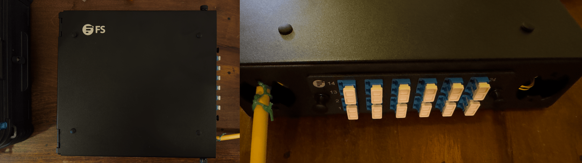
These are used wherever 12 or 24 fibers are terminating, while larger, 48 fiber versions, are used everywhere else.
As you can see, each box has a single plug on the outside for every cable coming into it. That’s called a patch panel. If you want to connect a fiber device such as a router to the network, you uncap one of the ports, you take a patch cable, and you then plug one end to the device, and another to that floor box.
If you want to “create” a single run that originates from the top left corner of the house and ends in the bottom right one, you just take enough patch cords, and you install them between ports of the same floor box, all the way to the other end.
This is what I like about this: you don’t need to install new cables every time you need something, you just find a path between the two ends, and then only add 30cm patch cables in the right locations to create this. All the cables are already there, pulled, terminated, fixed.
It’s the same principle as datacenter Meet Me Rooms (MMRs). If company A wants to connect to company B, you don’t need to run a cable, you already have them in place in both companies’ racks, and they end up in a single location, where you just patch them through.
I am now able to provision temporary circuits! If I want a connection from my office to the garage, to debug or troubleshoot something, or if I want a direct cable to a server room, I can do it in 5 minutes, without unwinding and winding large spools of cable, leaving doors and windows open wherever I cross.
Inside the Black Box
Now let’s peak into this box. What’s happening in there? How do two cables, with 12 fibers each, turn into a beautiful collection of ports?
The answer is simple: sweat, tears, and expensive equipment.
When you buy these, they come in two parts, like this:
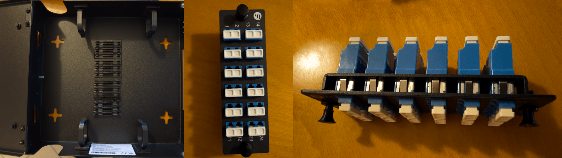
The left photo is the box, which is a simple metal housing. There’s not much to it, other than 4 plastic cable management arms, 24 slots in the middle, and some covers for the various holes they have where the cables enter.
On the right, you can see the patch panel. This has two sides, both of which have the same female connector. It’s essentially a female to female adapter.
Connectors
Optical fibers come with different types of connectors. These ones are called LC, and are small, reliable, and efficient. They’re also the most popular form factor for end devices. The other primary option is SC, which is twice as large, and is typically used in FTTH scenarios. The same product is available with SC as well, but it’d then fit 12 connectors, and not 24, like it is now.
The other choice on connectors is UPC vs APC. The former has the ferrule (connector tip) cut flat, perpendicular to the cable, while the latter has a small angle (hence the A in APC), whose primary job is to minimize reflections within the fiber. More on that later! The thing you need to know is that UPC is used for end devices, like routers, switches, and servers, while APC is preferred in PON deployments to offer cheaper FTTH, as well as long or repeated fiber installations.
Both can be turned into each other with a cable whose ends are different. If I chose APC for my setup, I’d need all cables to be UPC to APC for devices, and all patch cords to be APC to APC. Using UPC allows me to have a single patch cord and do everything. If I ever need an APC end, such as when a PON provider wants to bring service here, I can always leave a dangling UPC to APC patch cord in one of the ports and be mostly fine.
What’s more, I can remove ports in pairs, and make this a hybrid patch panel, which is 10 UPC + 2 APC, or anything else I want.
Finally, the color blue here signifies a UPC plug, while the color green means it’s an APC plug. If you mix them up, it won’t end up well for your cables.
Melting pigtails
From the photos above, all the fibers in the 12-core cables are coming in without connectors. We need to somehow turn a bare fiber into an LC connector. My former colleague Michael did it with Field Assembly connectors, which are mechanical and can be terminated almost without any tools. However, due to the scale of this project, as well as all the associated benefits of not doing it that way, I went with a much better, but also much more expensive method: fusion splicing.
Fusion splicing effectively melts together two optical fibers and joins them, as if they were a single piece of glass. You can join any two cables, as long as they are compatible. For example, you cannot fuse together a single-mode and a multi-mode fiber, but you can do that to a G.652.D and a G.657.A2 pair.
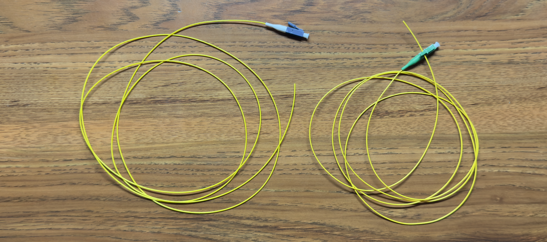
One end of our fusion splice is therefore the cable coming out of the wall, but what’s the other one? We need something with one end being a factory-installed LC connector, and the other end being bare fiber. Luckily, these things are for sale, and they’re called “pigtails”. Here’s a couple of them:
I won’t go into the process of splicing fiber, as it’s outside the scope of this blog post, and there and there are much better resources for it, but here’s a collection of photos from the process, along with a brief overfiew:
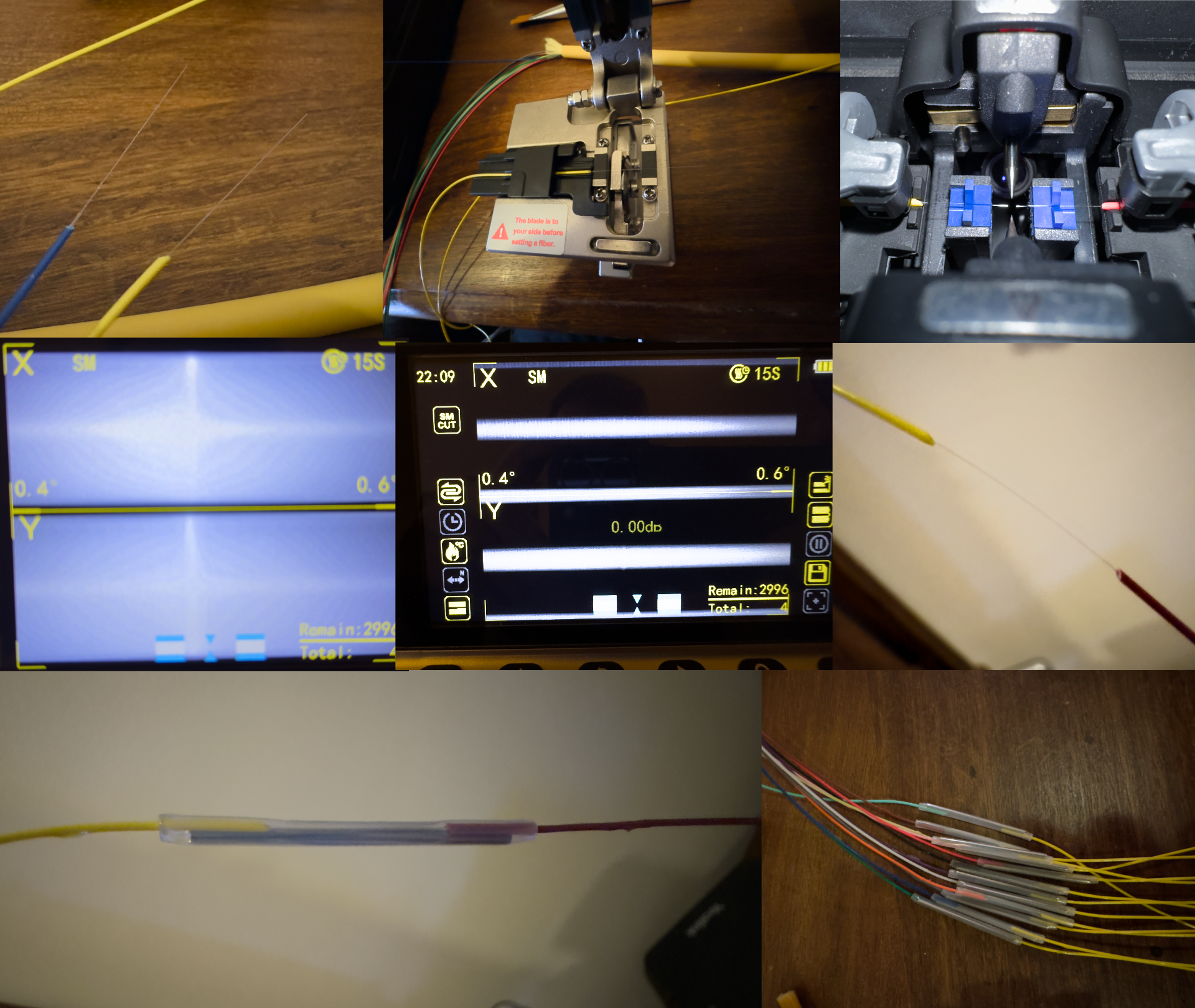
You first remove the protective layer of each fiber, and you then strip the
cladding, revealing the glass under it. You clean that with special wipes and a
high purity alcohol solution (A). You then use a high precision fiber cleaver
to cut each strand of glass to length, and ensure a straight cut (B). You then
align the two fibers you want to join within the fusion splicer, near the
electrodes that will melt them (C). The machine will align the two 9μm strands
in 3D space while you check for debris, cracks, bad cuts, excessive alcohol,
etc. using the 300x optical zoom, and if everything is fine, it will arc and
melt the glass (D), until the two cables are now one (E). It will also use
sophisticated AI heuristics to estimate the loss of signal due to
imperfections in the process. You then slide over a protective sleeve, over the
connection (F), and then bake the heatshrink tube (G) that you never forgot to
add, until it’s done. You now repeat the process 11 more times, and
congratulations, you’ve almost terminated one end of one cable (H)!
As you can see, this is a very long and tedious process, involving a lot of equipment, precision handling, and also a few mistakes and retries. I’ve had to splice almost 300 times for the entire project, but I remain hopeful that I now won’t need too much more for the immediate future :)
Assembling everything
You now hopefully understand what these 24 slots were for in these termination boxes. They were a splice tray, where these heatshrink tubes click into place for protection.
What’s left now is to click all 12 or 24 or 48 splices into place, and then plug each pigtail end on the inner side of the LC optical patch panel. What you’re left with is… art:
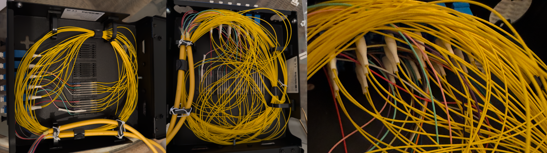
Now, I’m aware it’s a mess. There were also ways to make it better. But for a box I’ll hopefully never have to open again in my life, and taking into account the timeline of this project, personal mental health, and the effort of performing 300 splices, I am really happy with how it turned out!
I don’t want to complain too much, because there are others doing this amount of work in far worse conditions. Hurricanes, floods, snow and rain, and even war! I’ve been doing this in the comfort of my own house, while others have to do it with bombs exploding around them, to recover connectivity that’s critically needed and can really save lives.
Testing
It’s now done. After almost a couple weeks of work there are 11 cables, terminated to patch panels, ready to be used. Before that, though, they have to be tested. How can we do this?
Shining lasers
The easiest way to test if a light-bending glass tube can carry light is to shine a laser pointer on one end, and look for the (bright!) red light on the other end.
I did this to all fibers installed, and all but one worked! I now knew that they can carry visible light, but telecommunications networks are using infrared light. They also have much lower tolerance than “I can see a light shining” so that’s not enough.
Reflections!
My friend Pim has an Optical Time-Domain Reflectometer, or OTDR for short. Essentially it’s a precision instrument –and the second most expensive tool in this project by far– that shines light of various colors (wavelengths) into the fiber, and it can then very precisely measure the reflections in various parts of the cable, in connectors, splices, patch cords, etc. In the end, it can create a diagram of dB over distance, where distance comes from the time-to-reflection. Since he was willing to rent it to me, I put it to good use.
I performed 264 measurements, one per fiber, per cable, per wavelength, and looked at the results. To my disappointment, I identified a second fiber that failed the test. After a visit to the bird nests however, I was able to fix both of them, and their tests passed successfully. So much for never opening them again in my life ;)
For a worse-case scenario test, I created a wave accelerator (double pun intended). CERN built particle accelerators so I had to build photon ones. By adding the right patch cords in the right places, I now had 3 loops going from all the way to the top, to all the way to the bottom of the house, and back again, 12 times. I can now send light back and forth in a loop and measure it:
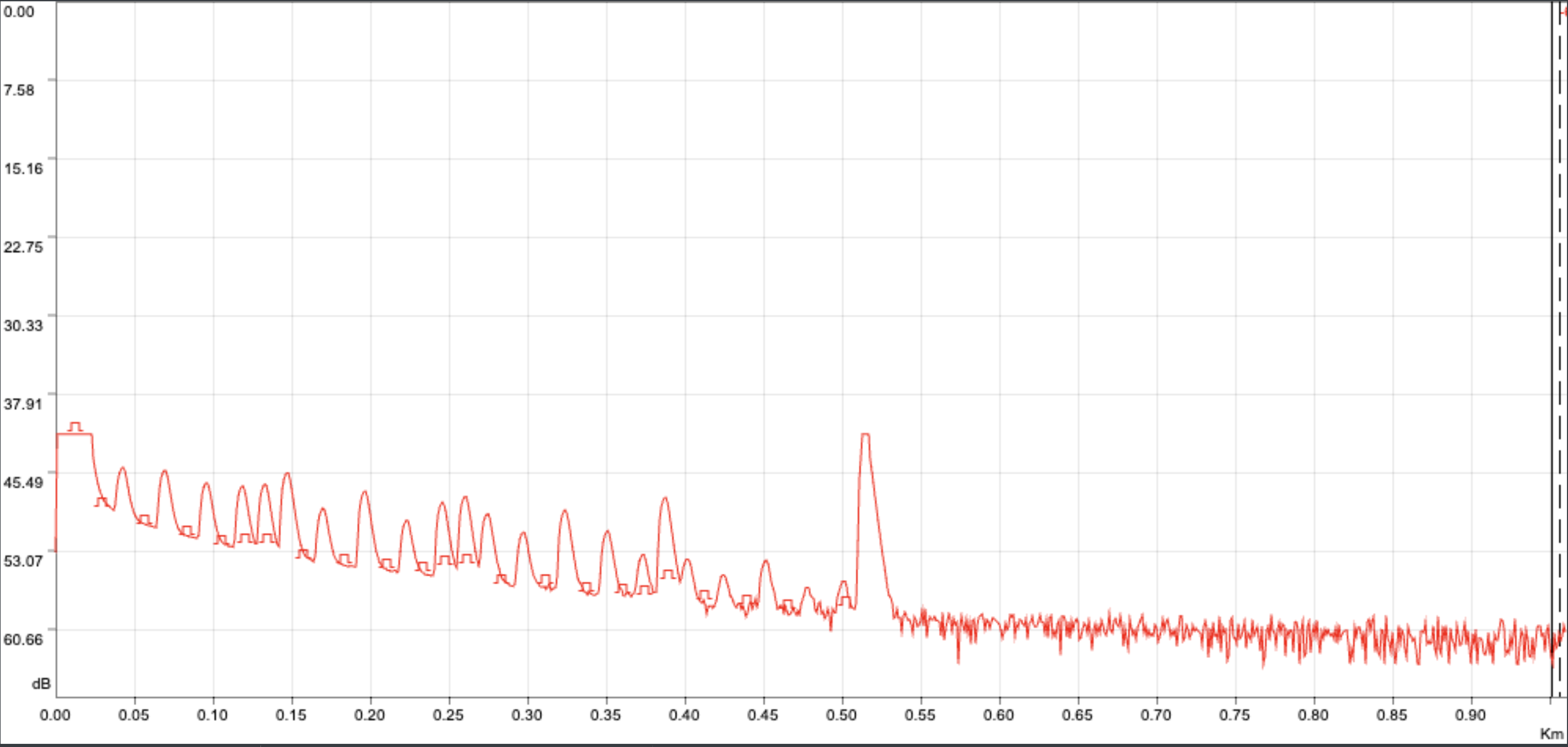
On the Y axis you can see the strength of the reflection within the cable coming back to the instrument, while on the X axis you can see time or length of cable. Around the middle of the image, there’s a single large reflection, and this is the end of the cable. This is caused by the UPC connector on my end, but at the other side of the cable, reflecting all the OTDR light back into the fiber. This is the benefit of APC connectors, where this wouldn’t happen. All these peaks between x=0 and that point are the various things in the way (patch cords, patch panels, splices, etc.).
Side note: the launch cable used was too short, within the OTDR’s dead zone. Therefore, the shape is accurate, but the Y axis values are not!
Ethernet
The final test involved some actual Ethernet usage. I moved around the building with a couple BiDi SFP and BiDi SFP28 transceivers and I tested all fibers methodically for link establishment. Because I let these run and collect measurements to ensure links are stable, I ran that on the four “wave accelerators”. The reason I used two speeds, 1G and 25G, is because 1G is “too simple” but 1310nm / 1490nm, while 25G is “not too simple” but 1270nm / 1330nm. It was a poor way to get some extra peace of mind.
The End Result
I now have ample of fiber connectivity in my home, everywhere I need it, and creating new physical circuits is very easy. I can probably provision them from anywhere to anywhere within a handful of minutes. This comes in addition to the existing IP and Ethernet networks that make expanding to new places or supporting new usecases already easy.
I have already migrated most of my equipment to operate on top of this, and it has worked reliably for close to 48 hours with 100% uptime! I am still leaving, for now, all of the old cabling in place, so it can serve as a failover or redundant path, if all else breaks. I am hoping that soon I’ll be running everything using the new Layer 1 network and I am certainly looking forward to the next time I’ll need a circuit, to verify if it’s as easy as I think.
Now that all the splicing is behind me, I’d rate this as a 10/10 in terms of customer satisfaction!
The Budget
After reading this post, you’re probably wondering how much this all cost. I am not sure I really want to know, so I’ll talk about another kind of budget: Link budget.
Every time there is an optical fiber link, depending on the laser you use to transmit at one end, and on the receiver in the other end, you have a certain “link budget”. If your transmitter can send “signal” at -3 dBm and your receiver can tell signal from noise at down to -15 dBm, then your budget is -3 - (-15) = 12 dBm.
Now that’s what you have to spend. If the link costs more, it won’t establish. If it’s borderline, it will be flaky, while if it’s cheaper, it will work at 100% of the speed. But what do you have to pay with this 12 dBm?
Fiber Length
Depending on the fiber standard and the wavelength used, single-mode fiber has a typical cost of 0.1dB - 0.3dB / km. You’re probably not going to see it go much better than 0.15dB / km for a single band.
For projects like this, where I didn’t even buy 1 km of cable, let alone use it, this cost is practically zero. Worst case, we now have 11.7 dB left to pay for other things.
Splices
Every time you perform a splice, there’s a chance that it won’t be perfect, and some signal loss will occur. If it gets too bad, you have the option to re-do it, in hopes of getting a better number, but in reality, it’s unlikely to matter. The average splice loss estimated by my splicer across the entire project is 0.01 dB per connection, but even if we take a crazy scenario of 0.15 dB, it’s not that much either.
Connectors
We are now entering some of the highest costs for a project like mine. Jumping from glass to glass is not very efficient, and can incur a loss of 0.3 dB per connector. Since a circuit can have as many as 10 connectors (worst case), that’s a solid 3 dB off right there.
If I had instead installed a cable directly, that would go down to almost 0.
Total
Taking a worst case circuit into account, and then doubling the losses, we’re still well under 10 dB, or, in other words, okay. I don’t think there are many optics with a budget smaller than that, but that’s the benefit of using 20km lasers for 50 meters ;)
This is no small number on paper, as it’s the equivalent of 30km-60km worth of travel in glass!
The real loss, even across the wave accelerators, is much smaller than that, so it’s of no concern, and links establish just fine, but suffice to say it’ll be enough for all house-local connectivity that I can reasonably throw at this.
There is however a potential edge case:
Splitters
If I ever want to use a provider that has a PON technology, and the fiber in the other end is coming from a few blocks away, from an FTTH cabin or a building, and I want to terminate it as far away from the building entry point (BEP) as possible, it could prove more challenging.
Passive Optical Networks reduce cost over active Ethernet deployments for lower speeds by using some physical splitters. Basically a single “switch” port is shared among 2 or even 128 customers. A typical case would be 32. All these people now have an aggregate 2.5/1.25 Gbps download / upload for GPON, or 10/10 Gbps for XGSPON. But we don’t care about speed, we want to see the link budget.
These 1:N splitters consume a lot of link budget! A 1:32 splitter can have an insertion loss as high as 17 dB alone. At 1:16 it is 13.5 dB, while at 1:8, if you’re very lucky, you can get away with 10 dB.
If the active ISP equipment is 2-3km away, and they use 1:32 splitters, there’s a loss of 20 dB before the fiber even gets in your installation. And then anything else you need is precious, and can’t be wasted.
Luckily, most PON transceivers have 25-30 dB of budget, so there’s still enough left, but it could be cutting it too close.
My current position is the following: if I ever have to do this, I’ll evaluate at the time, and worst case I just pull extra cable through the existing ducts. There’s plenty of space left there. Or, I can even pull two more 12-core cables and cut the maximum traversable connectors to half. It’s just graph theory.
Speeeeeed!
I now have 36 brand new, high quality fiber cables that can connect the top floor to the bottom. How fast can I run them if I had to?
BiDi
For most needs, a single fiber is enough to deliver end to end connectivity between two locations. The connectors that achieve this are called BiDi, which is short for BiDirectional. They transmit in one frequency and receive in another.
The fastest commercially available BiDi transceiver I can get my hands on is 100GBASE-BX. This allows for 100 Gbps of download and 100 Gbps of upload simultaneously.
Since I have 36 fibers, I could achieve 36x100G, or 3.6 Tbps in either direction.
Duplex
We’re now going to do something counter-intuitive: instead of using the 36 fibers for 36 connections, we’ll split them into 18 pairs. In each pair, we’ll use one fiber to upload, and the other fiber to download.
Although we now have half the connections, we can run them using 800GBASE-2LR4, which is actually 800 Gbps Ethernet. We can now upload 800 Gbps while at the same time downloading 800 Gbps, and this is per pair!
Across the entire project, we can now carry 18x800G, or 14.4 Tbps in either direction. Much better!
DWDM
If we study our fibers carefully, we’ll see that they’re (probably – I didn’t test thoroughly, but see no reason to doubt it) capable of carrying light at around 1200nm - 1600nm. Using only 800 Gbps per pair seems like a waste. We’re only using a few nanometers worth of capacity.
Dense Wavelength-division multiplexing, or DWDM as we like to call it, is a technology that allows the use of the entire spectrum of a fiber (pair). If 800 GbE needs a single color, we can now have a red 800 Gbps signal, an orange 800 Gbps signal, a yellow 800 Gbps signal, etc. through the entire rainbow of colors our cables can carry.
How many can we cram together in a single fiber pair? There are commercial solutions available that are in theory “off-the-shelf” that can give us a hint. Using almost all of the available spectrum, we can run 53x800G per fiber pair.
This is an astronomical number. Using current commercial technology we can achieve 18x53x800G, or 763.2 Tbps download and 763.2 Tbps upload simultaneously.
That’s gotta be it, right?
Cutting-edge research
Well, we can actually push these cables a bit more. Last month, researchers from NICT in Japan and NOKIA published a paper on how they achieved 301 Tbps using a single fiber pair! The work is interesting, although I must admit I don’t fully understand everything, but what we need to keep from it, other than the number, is that it works over existing fibers. Like mine.
So what’s the current theoretical limit? Let’s do the math: 18x301T = 5.418 Pbps.
This is probably enough for casual home use, at least for the near future, and if I ever feel like I’m reaching that, I can always spend a couple more weeks and add 36 more fibers to double it – I have all the materials after all :P
Real life
Now back to reality… Anything past Duplex will require equipment that costs orders of magnitude more than the house. But that’s true for any good datacenter, right? ;)
Just to give you an idea, picking the cheapest available hardware, “BiDi” would cost CHF 45,000 in optics and CHF 20,000 in switches, while “Duplex” would cost CHF 235,000 in optics and an NDA’d number of Swiss Francs in switches.
If any vendor wants to sponsor any of the packages available above, I’m happy to feature them in an upcoming post and talks!
In the meantime, I’ll be using 3 fibers, all at 10 GbE, while I wait. After all, for me, and for this, cables are much cheaper than any high capacity transport.
Future Work
In the same order I bought a few extra things. Treat them as a sneak peak of what may be coming:
It’s a couple kilometers of indoor low visibility cable, around 50 quad-LC or dual-SC plugs, as well as the thing I’m excited about the most: 2km of 4-core armored cable, suitable for underground and outdoor installation!
‘Til the next one!